E-Bike Hall Sensor Guide: How It Works, Failure Symptoms, Testing, and Replacement
If your e-bike stutters on startup, jerks under load, or shows a hall error code, the hall sensor on the motor is the likely culprit. These tiny magnetic switches tell the controller when to fire each phase. This guide walks through the exact diagnostics, a realistic branch point where your next step changes, and the concrete threshold where you stop DIY and call a shop.
How a Hall Sensor Works on an E-Bike
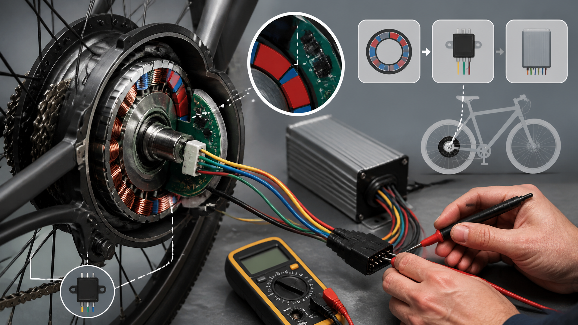
Three hall-effect sensors are mounted on the stator inside a hub motor (or mid-drive), spaced 120° apart. Each detects passing rotor magnets and sends a 0V or 5V signal to the controller. The controller uses these signals to time power delivery to the windings.
Rider outcome: With working sensors, pedal assist is smooth from zero. A failed sensor makes the motor vibrate, spin backwards, or refuse to start under load.
Common types: SS41 or AH276 bipolar sensors. They need a steady 5V supply and a ground wire from the controller.
Failure Symptoms (and What They Feel Like)
| Symptom | Rider experience | Likely cause |
|---|---|---|
| Motor stutters or jerks at low speed | Lurches on startup, then smooths above ~5 mph | One sensor intermittent or dead |
| Motor spins backwards when powered | Reverse rotation on a non-reversible controller | Wrong sensor order or a sensor stuck high/low |
| Error code on display (e.g., “06”, “HALL”) | Controller detects invalid hall pattern | Sensor shorted or open circuit |
| No assist at all, but throttle works | Motor free-spins but won’t move bike | All three sensors failed (rare) or wiring break |
| Intermittent cutoff on bumps | Assist drops out over rough pavement | Loose connector or frayed wire inside motor |
Real-world branch example: A rider reported “motor jerks only when starting uphill.” Testing revealed one hall sensor output stuck at 0V while the other two pulsed correctly. The dead sensor caused the controller to miss a phase every cycle. That rider replaced only that sensor and the problem was solved — but if the +5V supply had been low, the correct next action would have been to replace the controller instead of any sensor. That distinction is critical.
Testing Hall Sensors (Step-by-Step)
You need a digital multimeter (DC volts mode) and a small screwdriver to open the motor side cover.
Before You Start
- Disconnect battery and let motor sit for 10 minutes (capacitors discharge).
- Photograph internal wiring before removing anything.
- Check the controller connector: a bent pin or corroded terminal can mimic a sensor fault.
Testing Procedure
1. Identify the sensor wires. Typically five wires from the motor: Red (+5V), Black (ground), Yellow/Green/Blue (signal wires — order varies by brand).
2. Set multimeter to DC 20V. Connect black probe to ground (battery negative or motor case). Leave all sensor wires connected to the controller.
3. Power on the system. Turn on battery and display (motor will not spin; safe to test stationary).
4. Check the +5V supply. Touch red probe to the red wire’s pin on the controller side. Expected: 4.8–5.2V. Branch point: If below 4.5V, the controller’s voltage regulator is failing — do not replace sensors. Replace the controller. If above 4.5V, continue.
5. Probe each signal wire (yellow, green, blue) one at a time.
- With wheel stationary, each signal should read either 0V or 5V.
- Slowly rotate the wheel by hand. Each sensor output should alternate between 0V and 5V as a magnet passes.
- A sensor that stays at 0V or 5V regardless of rotation is dead. Replace that sensor.
Example test result: Yellow wire reads 5V constant, green and blue cycle. Bad yellow sensor.
6. Optional: resistance check (controller off, battery disconnected). Probe between each signal wire and ground. Typical reading: open circuit (OL) or very high (>1MΩ). Escalate threshold: A reading below 100Ω indicates a shorted sensor. Stop testing and do not power the system again until the short is cleared — it can destroy the controller’s 5V supply. Replace the shorted sensor immediately.
Common Mistake
Testing voltage with the connector unplugged — the controller may not power the sensors without a load. Always test with wires connected to the controller.
Replacement: What to Buy and How to Do It
Hall sensors are cheap (<$2 each) and widely available as **SS41** or **AH276** bipolar types. Buy two or three extras — they break easily during installation.
Steps
1. Remove the motor side cover. Usually 6–8 hex bolts. Tap gently with a rubber mallet if stuck. Note the O-ring orientation.
2. Locate the sensor board. A small PCB holds three tiny black packages (TO-92 or SOT-23 style). They may be glued in with epoxy or silicone. Use a heat gun or desoldering wick to soften and remove glue.
3. Desolder the old sensor. Use a fine-tip iron at 350°C for no more than 30 seconds per joint. Avoid lifting the PCB pad.
4. Insert the new sensor. Match the flat face orientation to the removed one — the marking (e.g., “SS41”) should face outward. Reversing orientation inverts logic and causes rough running.
5. Solder carefully, avoiding bridges. Use minimal solder.
6. Re-glue with RTV silicone or epoxy to prevent vibration failure.
7. Reassemble the motor, routing sensor wires away from rotor magnets. Check that no wire pinches between stator and cover.
Where People Get Stuck
- Soldering heat: Prolonged iron contact (over 45 seconds) can damage the sensor. Use a heat sink clip if needed.
- Orientation reversal: Mark the flat side of the old sensor before removal. If the motor runs rough after replacement, the sensor is likely backward.
- Wire routing: Sensor wires must not rub against the spinning rotor. Use cable ties or maintain at least 2mm clearance.
Success Check (Verification Before Ride)
After reassembly, confirm the fix before taking a full ride:
1. With the wheel lifted, power on and slowly twist the throttle. The motor should start smoothly from zero without jerking.
2. Rotate the wheel backward by hand while watching the display — no error code should appear.
3. Take a short ride (50 ft) at low speed. If it stutters, re-check sensor orientation or solder joints.
Stop/escalate if: after sensor replacement and all checks, the motor still displays the same error code or stutters consistently. Do not continue disassembling. The controller likely has a damaged hall input circuit. Replace the controller — further DIY diagnosis risks damaging new sensors.
FAQ (Common Follow-Ups)
Q: Can I ride with a failed hall sensor?
A: Only if your controller supports sensorless mode. Most e-bike controllers refuse to start without hall signals. Sensorless operation gives poor low-speed torque and may overheat the motor.
Q: Do I need to match the exact sensor model?
A: Use the same bipolar type (SS41, AH276, or equivalent). Unipolar sensors (e.g., A3144) only detect one magnetic pole and will not work.
Q: My motor has 12 pins but only 5 sensor wires. What are the rest?
A: The remaining pins are for temperature sensor (NTC), hall signal grounds, or unused. Ignore them unless you see a specific temperature error.
Q: Will a hall sensor failure cause battery drain?
A: No — hall sensors draw <10mA total. A shorted sensor may blow the 5V supply fuse inside the controller, but it will not drain the main battery when the bike is off.
**Q: Can I test hall sensors without a multimeter?**
A: Not reliably. A logic probe or oscilloscope works, but a $10 multimeter is the standard tool. Guessing leads to wasted parts.
Explore This Topic
- Back to Commercial
- Back to Truncation Fix
Related guides in this cluster: